Miscellaneous I/O
Discrete
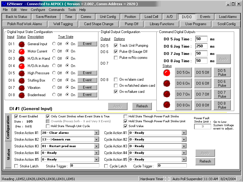
Some of the discrete inputs and outputs on the unit serve particular functions. Others can be configured for user defined alarms and annunciations. This screen allows the alarms or status inputs to be configured. Alarms and actions to take on true can be configured for each alarm if needed to perform particular function.
Analog
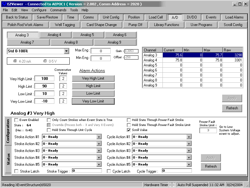
In the standard configuration, two miscellaneous A/D inputs are available to monitor pressures, temperatures, or levels. Alarms and actions to take on true can be configured for each A/D by this screen. Separate alarms exist for very low, low, high, and very high settings.
Standard I/O
Position input
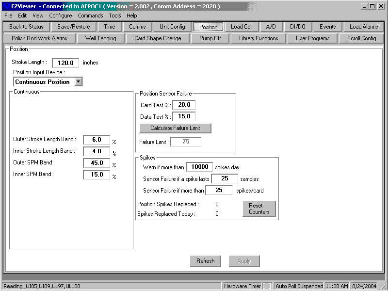
For most accurate cards, we recommend continuous position inputs be used. These can be configured here, along with limits to determine input sensor failures and alarms related to position.
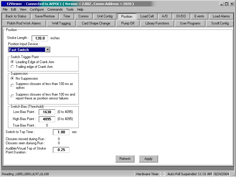
Frequently wells are configured temporarily with a continuous position input. This is then removed and a position switch is used to mark the top of stroke. This screen allows proper configuration of position switches.
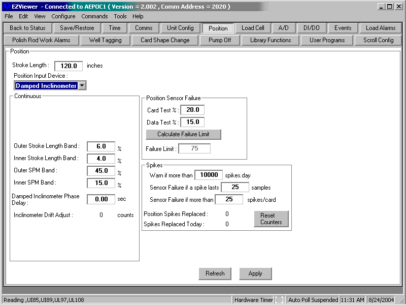
Inclinometers are becoming more common. These have some limitations at the top and bottom of stroke that must be dealt with by the software by smoothing out position values. In addition, there are different configurations for damped and undamped devices that are commonly found. This screen shows a sample configuration for a damped inclinometer.
Load input
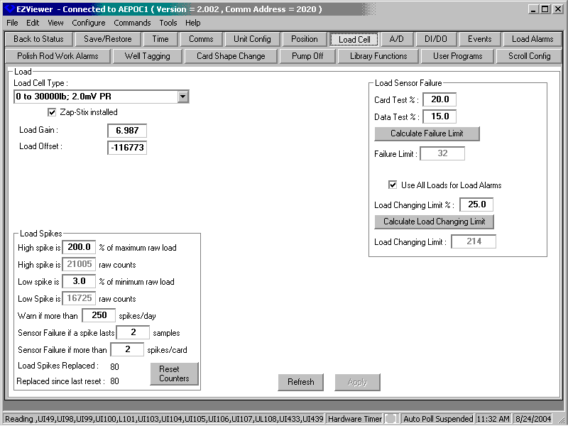
Polished rod load cells are the usual load measuring input device. This screen allows the user to select the range of the load cell being used. Limits can be set for load sensor failure and spike suppression.
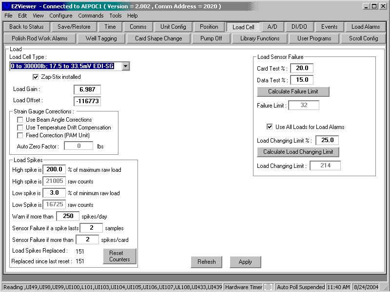
Strain gauge inputs are also frequently used, but have issues with drift as the sun heats the walking beam. This screen allows the loads to be properly calibrated and the drift compensation to be adjusted if the defaults are not adequate for a particular well. Limits can be set for load sensor failure and spike suppression.