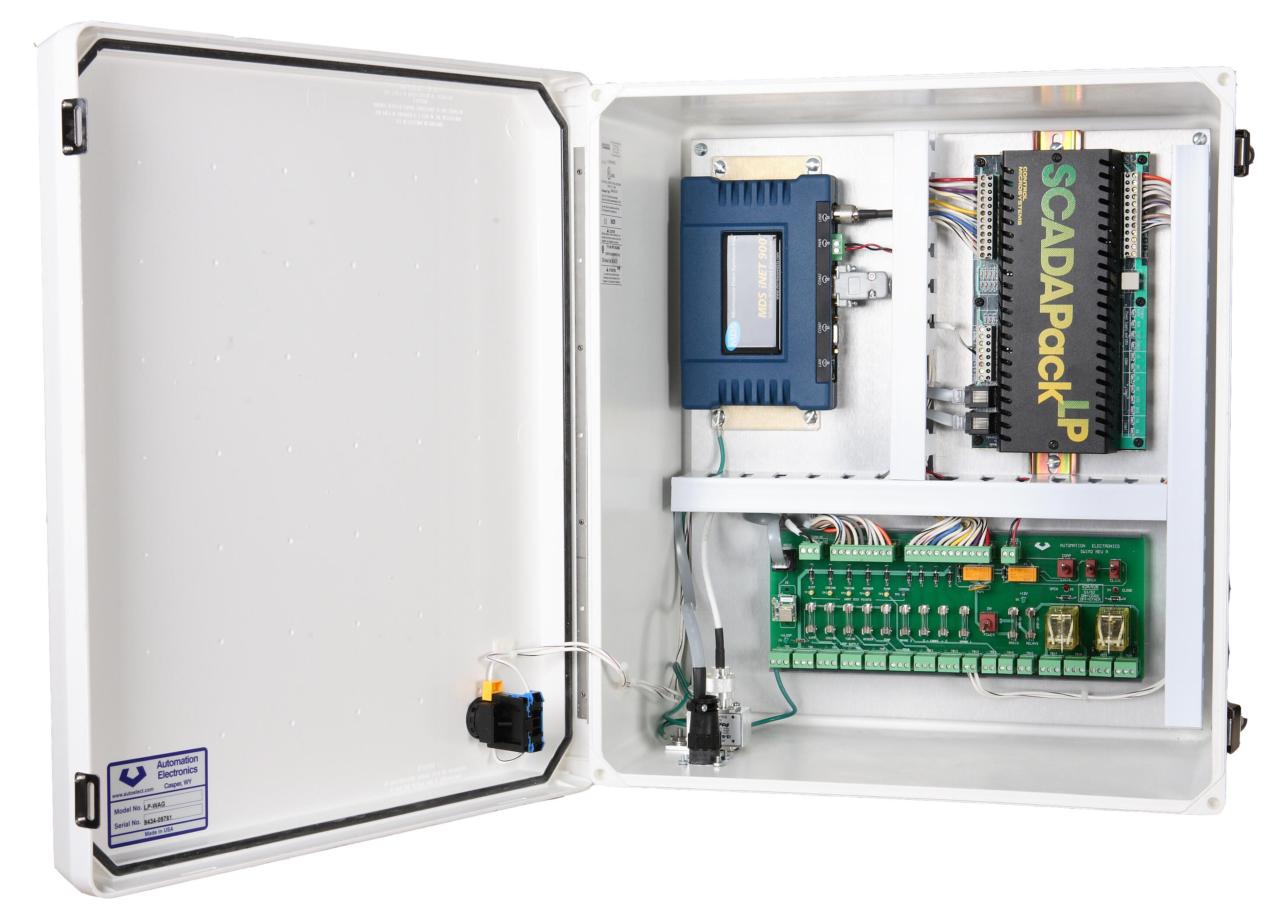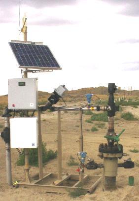

The Automation and Electronics, Inc. Water Alternate Gas Injection Controller (LP_WAG) is designed to monitor and control the injection of water or carbon dioxide at the wellhead.
User configurable pressure fall-off, step rate and step pressure test programs are provided. The LP_WAG controller is designed around our field proved WAG firmware and the Control Micro Systems SCADAPack® LP controller. The unit utilizes the NIST14 density equations to provide more accurate real time flow measurement in connection with a turbine meter or wedge type meter. Control modes available to the user are rate and/ or pressure limited with associated high and low set points. New features include selectable override control actions which allow the preservation of line pack and tubing pressure during low supply pressure situations or supply line ruptures.
The standard unit includes the SCADAPack LP controller and the Automation Electronics SCADAPack WAG I/O Module (SWIM). The SWIM incorporates the valve actuator pulse and direction control relays and the local actuator control switches. Labeled field terminals for all analog input transmitters and field status inputs are provided making installation quick and simple. All inputs are fuse protected.
Control parameters are configurable by the operator using an optional local interface, personal digital assistant or portable computer. A wireless Bluetooth interface is standard. The unit is supplied with typical parameters ready for specific application tuning. Setup parameters may also be downloaded from the host computer. A local / remote switch allows easy hardware access to the valve movement using toggle switches.
Features
Standard
- Flow control with pressure override
- Pressure fall-off test software
- Step rate and step pressure test software
- Direct turbine meter input
- Wedge type meter flow measurement for CO2 and H2O
- Manual valve override
- Local / remote switch
- NIST14 density calculation
- LEDs for easy status indication
- Wireless Bluetooth interface
Options
- RTU Link for rugged field PC
- 12 VDC @ 10 A battery backed supply
- 14 A-H/day solar supply
- Wire-line to wireless Ethernet communications
- Event log
Software
The LP_WAG application program is divided into the following modules:
- Elapsed time counter
- LCD and key pad user interface
- Time of day
- Gauge off time
- Field input scaling and alarm handler
- ESD control
- Pressure fall off test
- Control valve
- Control valve override
- Shut in and run-time totalizer
- End element buffer
- Override control modes
- Watchdog timer with recovery
- Long term trending
Specifications
| Mechanical | |
|---|---|
| Enclosure: | 18" x 16" x 8" NEMA 4X Enclosure |
| Environmental | |
|---|---|
| Operating temperature: | -40 to 158 deg. F (-40 to 70 deg. C) |
| Relative humidity: | 5 to 95% non-condensing |
| Power requirements | |
|---|---|
| Typical: | 12 or 24 VDC, 110 VAC and custom power supplies available. |
| CPU / Watchdog / Memory | |
|---|---|
| CPU: | 16-bit CMOS micro-controller and co-processor, 14.74 MHz clock |
| Watchdog: | Integrated |
| Memory: | 1 MB CMOS RAM, 512 kB flash ROM, 1 kB EEPROM |
| I/O interfaced through SWIM | |
|---|---|
| Turbine meter input: | Designed for use with low voltage turbine meter outputs. |
| Analog inputs: | Tubing temperature, header pressure, tubing pressure, casing pressure, differential pressure, battery voltage |
| Digital inputs: | Reset, choke open, choke closed, computer / local, two spare |
| Relay outputs: | Actuator direction, actuator pulse |
| Communications ports | |
|---|---|
| Operator interface: | 1 each wireless Bluetooth local operator interface standard |
| Host interface: | 1 each RS-232 Communications used with wire-line modems and licensed frequency, spread spectrum, and wireless Ethernet radios (19,200 baud maximum) |
| I/O: | 1 each RS-232 / RS-485 port for 4102MMT / 3095MMT multi-variable flow meter |