The ScadaPOC
The Automation & Electronics, Inc. ScadaPOC is a sucker rod pump monitoring and control system. This type of controller is often referred to as a Pump-Off Controller, or POC.

The ScadaPOC, as well as other pump off controllers like its predecessor the AEPOC, are mainly used to reduce excessive wear and tear on the pumping equipment. This excessive wear and tear occurs when a pump is continuously operated in a partially filled condition. This type of operating will cause many more failures without producing that much more fluid than a well that is idled for brief periods when there's not enough fluid to fill the down hole pump.
An early version of a rod pump controller was a simple percentage run time clock. This was set to run the well only a percentage of the time. The problem was setting the percentage. The fluid being produced by the well could be measured and the percentage of run time gradually reduced until the amount of fluid being produced started to drop. The percentage would then be increased back to where the well is producing at full capacity while not being run more than necessary. At that point, the percentage of run time was optimized for the well.
The problem was that this was a manually intensive process. After a few years oil well production depletes but the capacity of the pumping equipment remains the same. The well may only need to be operated 75% of the time where originally it needed to be operated 90% of the time. After a failure occurs, the well may need to be operated at 100% for a period of time to catch up, then dropped back to 75% after normal operations are restored. If a failure occurs in a nearby well then our well may have more fluid so the timer needs to be set to 85% of the time. If a water flood that pressures the formation were to go down, the timer may then need to be set to 20% until the water flood is brought back online.
Even if the ideal run time percentage could be determined, the field personnel really don't have the time to be constantly adjusting manual run timers. What ends up happening is that the pumps are usually operated way too much which preserves the production, but causes excessive wear and tear on the equipment, increased failures, and uses more electricity than needed. Also, in other cases the pumps could be operated too little where production is being lost. What is needed is a way to adjust the run time automatically.
The ScadaPOC was designed to suit this purpose by determining when a well is not pumping with a full stroke of fluid. This is referred to a pump off. The ScadaPOC detects these pump offs and idles the well for an adjustable amount of time between pump offs acting like a percent run timer that automatically adjusts itself. This minimizes the wear and tear on the pump, rod string, tubing, gear box, and all of the other moving parts of the pumping equipment. It also saves on the electricity used to produce the oil without sacrificing the fluid produced by the well.
Dynamometer Cards
There are many ways, proprietary secrets, and more than a few wild theories and opinions as to how to detect a pumped off condition. The real test of a pump off controller is consistency and reliability in detecting a pumped off condition. The ScadaPOC and its predecessor the AEPOC have used the surface dynamometer card to successfully control pumping units in thousands of installations for numerous fields, depths, pumping unit configurations, oil types, water cuts, and other oil well variations.
The dynamometer card is generated by measuring the load on the polished rod compared to the position of the polished rod string as the pump goes up and down (See Figure 2.) The shape and features of a dynamometer card vary with pump fill, along with well depth, pumping unit configuration, rod string taper, pump speed and many other conditions. (The card shape can also vary with problem conditions such as emulsion, failed tubing anchors, pump valve leakage, asphaltines, paraffin buildup, trash in the pump, flow line pressure, etc.).
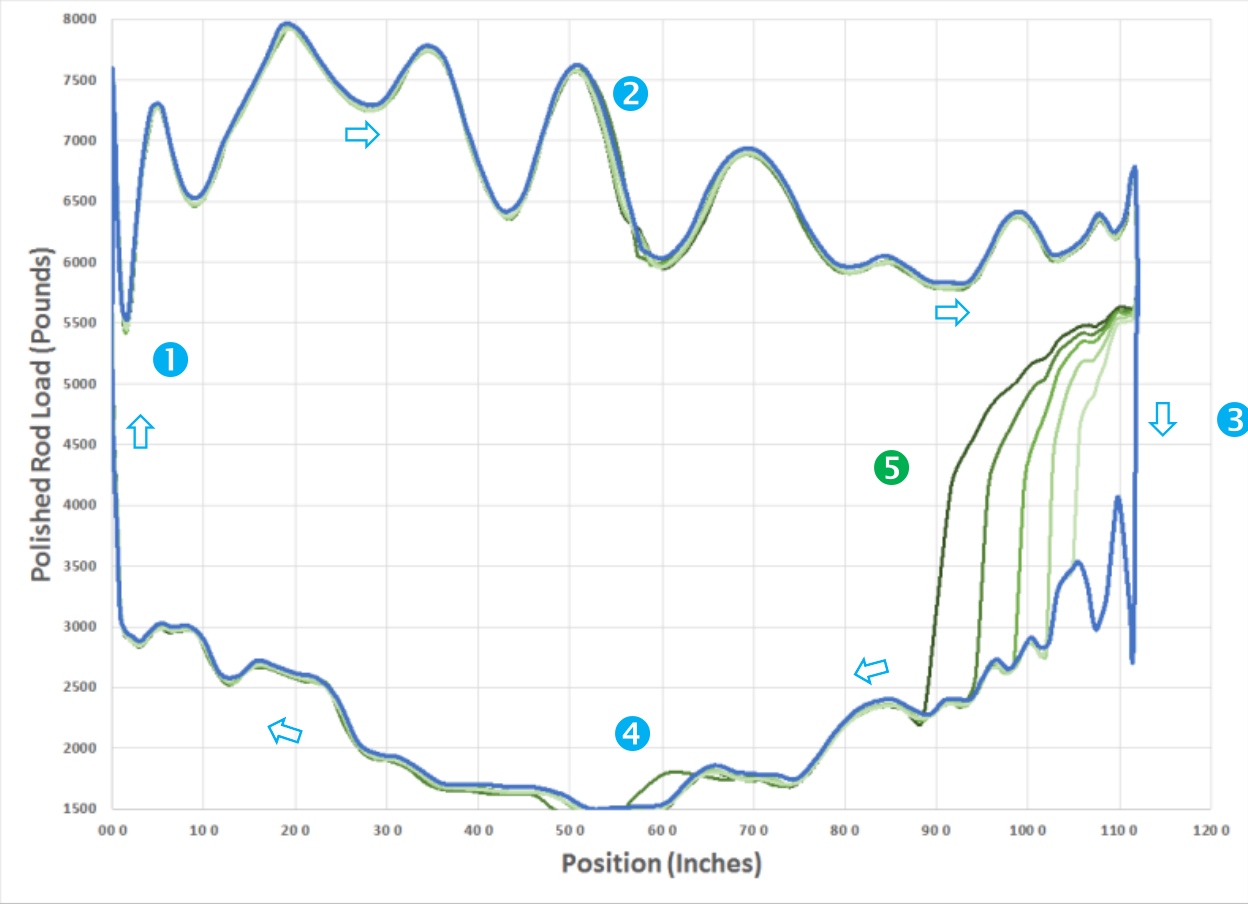
Reading dynamometer cards does take some training and experience, but it is not that hard to see a pump off condition. Figure 2 shows the dynamometer cards from a shallow well, where we can most easily see what happens as the well pumps off. The blue card represents a well that is pumping with a full stroke of fluid. The loads and positions trace a clockwise route around the dynamometer card (indicated by the arrows as the pumping unit goes up and down.
At the very bottom of the stroke (left side of the card), the pump starts pulling the rod string up (the area marked 1 in Figure 2.) The traveling valve in the pump closes, the standing valve opens, and the rod string takes on the load of the fluid in the tubing. This shows up on the dynamometer card as the load on the polished rod increases.
In the area marked 2 in Figure 2, the polished rod is being pulled up through the upstroke. The rod string acts as a dampened spring so we see waves in the load as the rod string stretches and relaxes on the way up.
When the pump reaches 3 in Figure 2, it finishes the upstroke and starts on the down stroke. This downward motion causes the standing valve to close and the traveling valve to open. The load transfers from the rod string, where it is measured, to the tubing, where the load is not measured so there is a drop in the load on the polished rod as it first starts down.
During the rest of the down stroke (marked 4) the rod string travels back down to the bottom of the stroke as the pump pushes its fluid into the tubing. Once again, the rod string acts like a spring causing some oscillations in the load.
This process repeats itself over and over again with each stroke, until the pump catches up with the fluid built up in the well. At this point, the pump can no longer completely fill with fluid so it sucks in more and more gas as it pumps less and less fluid with each stroke. As the pump starts the down stroke (in area 5) it is now only partially filled with fluid. This is shown for successive strokes with the green dynamometer cards in Figure 2.
At the start of the down stroke for the partially filled pump, the standing valve closes but the traveling valve doesn’t open up until the gas in the pump compresses. This keeps the loads from being transferred from the rod string at the very start of the down stroke like it does when the pump is completely filled with fluid. After the gas in the pump finishes compressing the travelling valve finally opens which causes the loads to be transferred to the tubing later in the down stroke instead of at the start. The less the pump is filled with fluid, the further into the down stroke it is when the load drops off.
When the transition of loads to the tubing happens at the top of a stroke, as it does for a full pump, the rod speed is near its minimum. This minimizes the stresses on the pumping equipment. When this transition of loads happens closer to the middle of the stroke, the rods are travelling faster. This causes more of a shock as the forces that change are more abrupt, creating more of a pounding on the rod string. This is referred to as "fluid pound," which can cause more compression force on the rod string which was really designed for a tension type load. This pounding causes increased rod string, tubing, and pump failures which increase the long term costs of operating a beam pump.
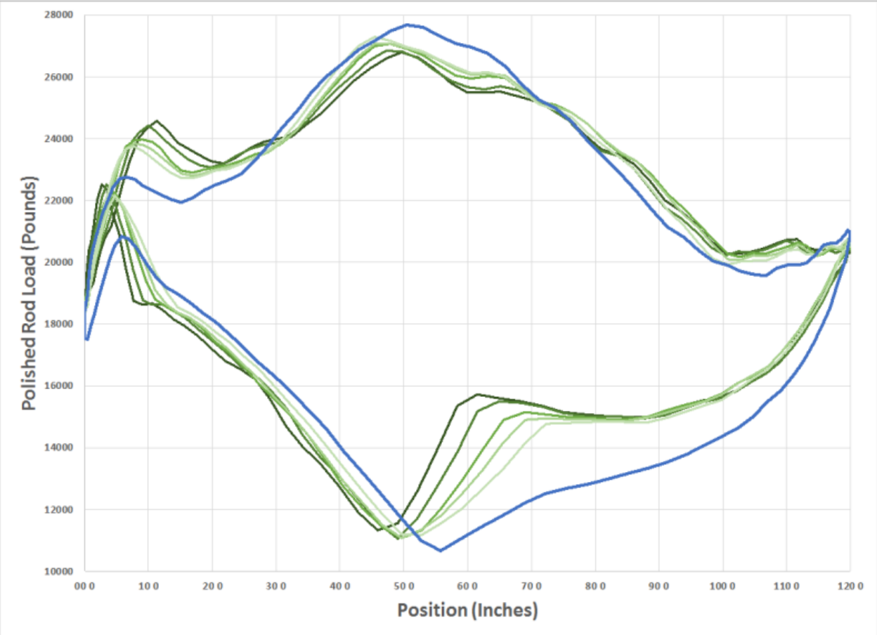
Figure 3 shows the dynamometer cards from a much deeper well. These cards are also from a different style of pumping unit. While the shape appears much different than those from the shallow well above, we can still see an isolated area where the progression of the partial pump fill affects the dynamometer card.
The extra length in the rod string simply delays the loads from being transferred to the rod string on the surface dynamometer card until the pump is further in its down stroke. The effect of the pump off happens in a different part of the dynamometer card for a deeper well than shallow wells. This is caused by the time it takes time for the drop in loads to propagate from the down hole pump up to the polished rod at the surface. There are also fewer oscillations of the loads during the upstroke and down stroke from the spring effect of the rod string, but these are more pronounced on a deeper well. This is because the rod string is much more massive and the longer, which makes it stretch and relax more than in a shallow well.
Each well, especially the deep wells, has a different area of the surface dynamometer card that shows the well is pumped off. With a little practice with similar wells and similar equipment an operator can see what part of the dynamometer cards best shows the pump off effect.
Detecting Pump Off
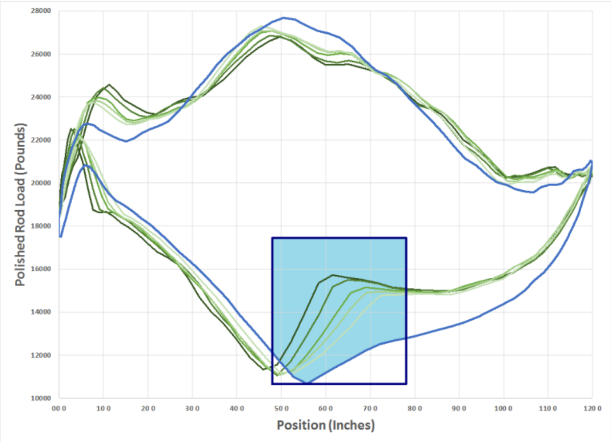
The ScadaPOC uses a rectangle around the part of the dynamometer card that changes during a pump off. This pump off rectangle is shown in Figure 4. As each card is gathered and processed, the ScadaPOC calculates the relative area of the rectangle that is also inside the dynamometer card. In the case of the well in Figure 4, the full card in blue has 84% of its area inside the dynamometer card (the area highlighted in light blue.) A pump off limit is then set so the pump off is detected when the area inside the card and rectangle drops below that limit (as in the case of the green pump off card.)
The size, location, relative area, and number of strokes where the area inside the card that is below the limit are all configurable and can be set for each well individually. This allows the operator to accommodate the well's depth, pumping unit type, rod string taper, and other variations with a highly reliable and consistent pump off detection.
While each well should be configured individually, the variations in pumping unit configurations, rod string tapers, and depths tend to be similar for a large percentage of the wells in a particular field. Most of the ScadaPOCs within a field will usually end up with a similar pump off rectangle configuration for most of the wells, with only a change in the percentage limit for the individual well.
Other Advantages to the ScadaPOC
There are many reasons to use ScadaPOCs that don't have anything to do with pump off detection and control, but with oil field optimization.
Failure Analysis
Continuing to operate a pumping unit with problems may have limited production and could also damage the pumping equipment. The origins of the dynamometer card and pump off detection algorithm came from when oil companies were trying to determine what was causing excess failures in some of their wells. The ScadaPOC not only detects pump off in the dynamometer cards. It also has a flexible means of detecting alarms and failures. The detection limits of alarms can be adjusted so that alarms are reliably detected while limiting nuisance alarms. The way in which the ScadaPOC responds to alarms is also highly flexible so the field can set the various conditions to alarm, shut the well in, cycle the well, save dynamometer cards, etc.
As these alarms and failures occur, the ScadaPOC retains the dynamometer cards leading up to the alarms and failures as well as a log of events. The alarm and failure dynamometer cards and event logs can be reviewed to help to determine what the original cause of a failure was and when things happened. This saves maintenance costs as the real sources of well failures can be determined and fixed before they cause repeated well failures. Further minimizing costs and maximizing production.
An example of how this can be used is a well that has an emulsion problem. If the emulsion wasn't detected and the pump was still run while emulsified, an abnormally high work would be required by the pump, and an abnormal load range would be placed on the rod string by the emulsion. Eventually the high work and abnormal loads would case a failure on the pumping unit. If the field replaces the rod string without fixing the underlying emulsion problem, then there will soon be another failure. What the field needs to know is the underlying cause of the repeated rod string failures.
The ScadaPOC is able to detect the extra work from an emulsified well, and saves the dynamometer cards leading up to the emulsion alarm showing how much extra work was required, and the increased load on the polished rod. The ScadaPOC can be configured to just alarm on emulsification, shut the well down, or open a valve that releases an anti-emulsion chemical into the casing. The ScadaPOC's event log would show that the emulsion occurred and when, along with the calculated work that generated the alarm and the work limit. It would also hold the dynamometer cards leading up to the emulsion alarm for every time the alarm was tripped. The ScadaPOC would also have logged when the load alarms and dynamometer cards from when the load alarms were tripped as well as when the rod part was detected. This is only one example of how the ScadaPOC can be used to reduce repeated failures, not every field or well has an emulsion problem, or would ignore alarms as they occur.
There will always be a limit to the life of the pumping equipment, so eventually it will fail on its own. With the ScadaPOC the field can see the dynamometer cards leading up to alarms and events and perhaps determine the underlying cause of repeated failures, giving the field the diagnostic tools to see and fix the right problems rather than just fixing the rod strings.
Telemetry and SCADA
When a well fails, it's not always readily apparent. A deep rod part doesn't keep the pumping unit from going up and down, and the well can even produce some fluid. So, when a failure occurs, someone must first determine that there is a problem. If the field is muddy, there may be times when an operator can't easily get to all of their wells. Depending on the field, the time of year, the roads, and other problems the operators are dealing with, there may be some time before a failure is discovered. Eventually the drop in production will be noticed, but not before some production has already been lost.
Manually recording pump run time and other data is easily influenced by gaps in the data, errors in taking the readings, and errors entering the readings into maintenance records. Oil field engineers and managers need accurate and reliable data to determine where to best expend company resources.
The ScadaPOC can serve as a part of a Supervisory Control and Data Acquisition (SCADA) system. These systems allow oil field operations to remotely monitor and control the operation of the ScadaPOC from a host computer.. As computer networking and data communications become more important, telemetry and SCADA capabilities are more important to oil field operations.
Remote data gathering (telemetry) is implemented through the ScadaPOC as it serves as a Remote Terminal Unit (RTU). These telemetry functions allow the ScadaPOC to be polled for well status, run times, and a whole host of other data through a wide variety of communications networks. The ScadaPOC's remote control (SCADA capabilities) allow the field to start, stop, and alter the operating mode and set points over a communications network.
This allows the oil field operators to quickly determine when a well has a problem, remotely diagnose well difficulties, and easily gather accurate operating data. It also allows for remote restart operations when possible. Oil companies without SCADA are forced to spend more on vehicles for operators, road improvements, as well as suffer more production losses before problems are discovered.
Monitoring and Control of Other Well Site Systems
The ScadaPOC is also equipped with extra inputs and outputs for monitoring and control of other well site systems. This allows the ScadaPOC to be a well site controller, and not just a beam pump controller.
In addition to the digital inputs needed to monitor the standard pump Hand/Off/Auto switch status and motor running status, there's extra inputs and outputs that can be used not only for telemetry, but can be used for well site control. Typical applications include a start push button that will restart the pump, as well as flow line, vibration, bradenhead, and stuffing box switches that will stop the pump, to other switches that simply report the status of wellhead systems (such as valve open or closed.)
Along with the analog inputs that are required to measure polished rod loads and positions, the ScadaPOC has extra analog inputs that can be used to monitor other well site data, such as casing and flow line pressures, tank levels, or temperatures. These readings can be used for simple status, they can be used to generate warnings, or they can be used to shut down the well (such as the case with a high flow line pressure, or tank level.) Separate alarms, very high, high, low, and very low are provided for each of these analog inputs.
Extra digital outputs are also available for use beyond the one that it takes to turn the pump motor on and off. Some examples for the use of these include an alarm beacon, external hour meter, chemical injection valve, an alarm reset output and speed control Variable Frequency Drive (VFD) or soft start, or a backup hardware timer.
An analog output is also available for control of a VFD speed, or perhaps a chemical injection pump.
For most of the control options, these extra inputs and outputs can be configured for what is useful by enabling setting up preset events and alarms. If that doesn't provide enough flexibility, the ScadaPOC can also be programmed in C script for added flexibility in detecting alarms and events as well as how to react to these conditions.
Economics
The ScadaPOC does have its costs: the controller itself; the electrical installation; the end devices that are used to measure load and position; the training of field personnel; maintenance of the controllers and transducers; and finally ancillary equipment such as laptops or tablets. Depending on the optional systems that are used in the field, there's also: the radio networking; optional transducers and their associated wiring; programming and maintenance of a host system.
To offset these costs, there's the benefits of the ScadaPOC: the reduced work-over rigs, rod strings, tubing and loss of production caused by excessive pumping equipment failures (from both operating under fluid pound as well as other conditions that could have been picked up by the controller); electric utility charges for operating the pumping equipment with only partially fluid filled strokes; the extra equipment failures that could have been diagnosed with a knowledge of how the equipment actually failed (such as fixing an emulsion problem rather than fixing a repeated rod string failure.)
The costs and benefits depend quite a bit on field specifics. A shallow well can be fixed much quicker and cheaper than a deep well. Deeper wells need to be monitored and controlled closely as they operate closer to the limits of the pumping equipment, while shallow wells don't push these limits as much.
Depending on the well depth and equipment types, the costs of just one rod string failure can easily outweigh the cost of a ScadaPOC. If it saves one failure per year, it can more than pay for itself in that first year. What if the well currently fails more often than that? How much more will a ScadaPOC save over its life when you also include the loss of production, rod strings, tubing, electricity, as well as wear and tear on field equipment and operator time? Add to that the benefits of having accurate and detailed pumping data on a regular basis.
This is how oil producers return the most value to their lease owners, partners and shareholders. This is how it also can survive when oil prices fall.